Rental Services
Bundle Pullers/Extractors
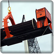
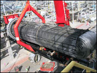
The Aerial tube bundle extractor is suitable for use on all Plate and Tube Heat Exchangers up to 2.75 mtr. Diameter and maximum bundle weight of 45 T at 12mtr length. The Aerial Tube Bundle extractor uses a special lifting frame, which is constructed in such a way that it has a maximum reach into the construction. The load is trimmed using an Aerial balancing Cylinder which makes it also easy to off load the bundles when the extractor is putdown on the ground. Due to the use of a pulley hook mechanism and 2 butt plates which are clamped against the extractors shell, the massive power of 45,000 kgs. Is compensated against the shell flange not against the structure.
Description
- The unit is self-supportive due to the use of an air-cooled diesel engine. The engine drives the hydraulic pump and is equipped with a spark arrester. All hydraulic functions are remotely controlled for increased safety of the operator.
- The extractor is fitted with a hydraulic which, which can pull/install the bundle in one stroke.
- The hydraulic which is equipped with a vertical moving prism sheet which eases the operation considerably.
- Because of the slim construction of the superstructure, accessibility to the exchanger and its surrounding obstacles are increased and furthermore there is no need to disassemble the superstructure while lifting the bundle out of the extractor.
Technical data of Bundle Extractor
| Measurements (approx) |
| Weight of extractor – unloaded |
12500 kg |
| Height of Operational position |
3300 mm |
| Width of extractor |
1400 mm |
| Length of extractor |
9000 + 3000 mm |
| Max. Straight tubes length |
12000 mm |
| Max. tube sheet diameter |
2750 mm |
| Max. force applied with winch |
45000 kgf |
Torque Wrenches
|
|
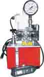
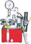
Pneumatic Drive Hydraulic Pump
Pressure Range : 700 Bar / 10,000 Psi,
Flow Rate 13.1 LPM
|
|
|
|
Electric Operated Hydraulic Pump
Pressure Range : 700 Bar/10,000 Psi,
Flow Rate 13 LPM
|
|
 Casset wrench Casset wrench
 Square Drive Square Drive
|
|
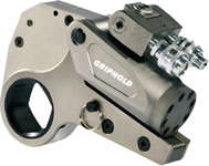
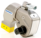
Torque Tools
Size of nut 22 – 200 MM
Torqueing value 430 – 70000 Nm
|
|
|
|
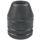
Socket
Deep socket : 40 to 100 MM
Impact socket : 22 to 145 MM
Accurate up to +- 3% with standard torque chart supply.
|
Hydro-jetting Machine
- High pressure jet cleaning/hydro blasting of tubes/surfaces upto max 20000 psi.
Hydro-jetting is a process to clear blockages in pipe system and is mainly the first approach to clear blocked lines. According to the possibility of the blocked line, hydro-jetting will solve the problem and thereafter routine maintenance will make the line funtioning properly. Our hydro-jetter system have a heavy-duty power nozzle attched to high pressure. Operating at approximately 20000 psi, the hydro-jetting will destroy the most stubborn line blockages and efficiently scour the entire pipe.
|
|
|
|
|
|
|
|